|
 |
 |
 |
Optical Simulation Software
Optical Disk Media Evaluation Hardware
Considering purchase of the product, please from Contact Us page.
|
 |
 |
 |
 |
|
To view or print the PDF files, you must have Adobe Reader ®. Click here to download.
|
|
|

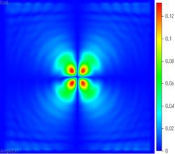
4.bumps
1. Description:
Focused beam, wavelength 650nm,
incident through a substrate on the aluminum layer with two
sphero-cylindrical bumps, centered at (x,y)=(-300nm,0nm) and (300nm,0nm)
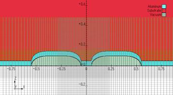
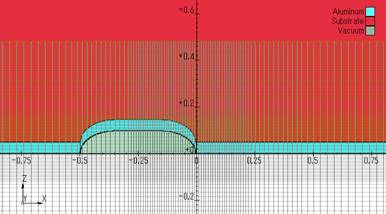
Structure, top to bottom:
layer1 n=1.5
layer2 50nm Al, n+ik=2+7i layer plus 2 spherocylindrical bumps
with total length=500nm, width=300nm, height=100nm
layer3 n=1.0
distance from Al layer top to R plane=280nm
Lx,y=12*lambda/1.5=5200nm
Input files:
parameters.input
boundaries.input
geometry.input
material.input
S000.DAT - input beam distribution computed with DIFFRACT COMMAND.DAT
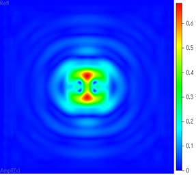
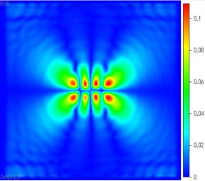
Output files:
fdtd.bumps.r - computed reflected field distribution in xy-plane
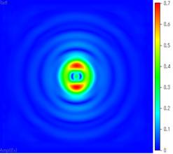
2. Description:
Focused beam, wavelength 650nm,
incident through a substrate on the aluminum layer with a
sphero-cylindrical bump, centered at (x,y)=(0nm,0nm)
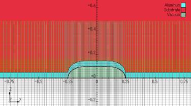
Structure, top to bottom:
layer1 n=1.5
layer2 50nm Al, n+ik=2+7i layer plus 2 spherocylindrical bumps
with total length=500nm, width=300nm, height=100nm
layer3 n=1.0
distance from Al layer top to R plane=280nm
Lx,y=12*lambda/1.5=5200nm
Input files:
parameters0.input
boundaries.input
geometry0.input
material.input
S000.DAT - input beam distribution computed with DIFFRACT COMMAND.DAT
Output files:
fdtd.bumps0.r - computed reflected field distribution in xy-plane
3. Description:
Focused beam, wavelength 650nm,
incident through a substrate on the aluminum layer with a
sphero-cylindrical bump, centered at (x,y)=(-250nm,0nm)
Structure, top to bottom:
layer1 n=1.5
layer2 50nm Al, n+ik=2+7i layer plus 2 spherocylindrical bumps
with total length=500nm, width=300nm, height=100nm
layer3 n=1.0
distance from Al layer top to R plane=280nm
Lx,y=12*lambda/1.5=5200nm
Input files:
parameters1.input
boundaries.input
geometry1.input
material.input
S000.DAT - input beam distribution computed with DIFFRACT COMMAND.DAT
Output files:
fdtd.bumps1.r - computed reflected field distribution in xy-plane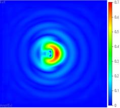 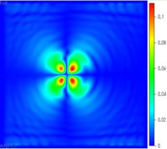
|